Greetings!!!
One afternoon, after finishing my meal, I picked up the ABB Switchgear Manual, 12th Edition (2012), and started reading. I came across many topics — units of physical quantities, chemical and technical values, strength of materials, blah blah blah…
After reading all the basic concepts. I reached the main topic: calculating short-circuit currents in a three-phase system as per to IEC-60909.
But before entering the short-circuit current calculations, it introduces the major terms and definitions related to IEC-60909 fault calculation.
That’s when it hit me. If a ABB switchgear manual forces me to stop and learn the vocabulary before doing a single calculation. I wondered how much it is important to understand the terms and definitions for every electrical engineers.
So, I’ve decided to explain these terms and definitions in my own style. Not in academic jargon especially for electrical students and engineers.
Introduction
The international standard IEC 60909 provides guidelines for calculating short-circuit current in three-phase systems.
Don’t worry!!! it’s also fundamentally applicable to single-phase short-circuit currents, since it covers both balanced and unbalanced short-circuit faults.
The goal of this post is to explain the key IEC 60909 terms before the attempting the short-circuit current calculations.
This will simply give you the in-depth knowledge needed to perform well in short-circuit calculations.
Term and Definitions as per IEC 60909
Core definitions: The basics
Short circuit
According to IEC 60909, understanding the term “short circuit” is important in power system analysis.
The formal boring definition in IEC 60909 may sound long and technical, but the core meaning is simple:
A short circuit occurs when two or more points in an electrical circuit that are normally at different potentials become accidentally or intentionally connected and make a very low impedance path.
This above short-circuit event creates a condition where current flows abnormally high compared to normal flow.
In simple terms, current always follows the path of least resistance. When a fault creates a much easier path than the intended load path, a high surge current flows through that least resistance path instead.
Now— why is it called a “short circuit” and not a “long circuit”? Just for fun. It is also my biggest doubt.
Always note that current is not “choosing” a shorter distance, but a lower resistance/impedance path. Under fault conditions, a new low-impedance path appears that effectively bypasses the normal load path. So compared to the intended circuit, the current takes a “shortcut,” resulting in a sudden increase in current magnitude.
In short, “short circuit” doesn’t refer to physical length — it refers to an electrically shorter (lower-impedance) path.
Short-circuit Current
When we talk about short-circuit current as per IEC-60909, the below explanation best suits
The abnormally high current or fault current that flow during a short-circuit condition at a two or more point is called short-circuit current.
Prospective short-circuit current
As per IEC 60909, the term prospective short-circuit current can be rewritten as below for better understanding.
Simply put, it is the maximum current expected to flow during a short circuit. This peak current occurs right at the fault point, where electrical impedance drops to nearly zero using ohm’s law.
Note: While textbooks often use confusing phrases like ‘replaced by an ideal connection,’ all it really means is that we are calculating the worst-case scenario where the fault point has absolutely zero resistance.”
Element of the fault waveform
Symmetrical short-circuit current
As per IEC 60909, understanding the term symmetrical short-circuit is very crucial since it going to repeat in most of the places and design calculation stage.
Root-mean-square (r.m.s) value of the symmetrical alternating current (a.c) component of a prospective short-circuit current (highest expected value), excluding direct-current (d.c) or aperiodic component.
Note: RMS Value is a big topic. To remember it in simple way you can use this 3 words “Effective heating current”.
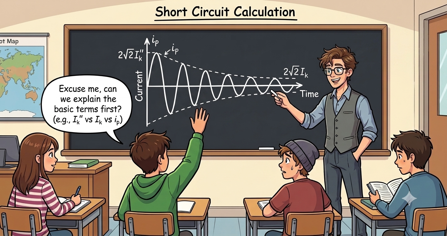
Initial symmetrical short-circuit current (Ik”)
Yes, same symmetrical short-circuit current (Ik”) is repeated again with the word “initial” in front.
The Root-mean-square (effective heating current) value of the symmetrical a.c component of a prospective short-circuit current at the moment the short circuit occurs if the short-circuit impedance retains its value at time zero.
Initial symmetrical short-circuit power (Sk”)
The term initial symmetrical short-circuit power (Sk) is also essential to calculate fault level at a specific point.
A imaginary quantity calculated as the product of initial symmetrical short-circuit current Ik”, and the nominal system votage (Line to line) (Un) along with the factor √3.
Note: Since it is an imaginary value, engineers always prefer to match the actual short-circuit fault level, so they use actual network impedances to correct this.
D.C (aperiodic) component short-circuit current
The term DC (Aperiodic) component short-circuit current is also known as decaying DC component (iDC)essential to calculate fault level at a specific point.
The DC component is the moving axis the short-circuit current waveform wobbles around — literally the midpoint or mean value between the waveform’s upper and lower envelope curves.
During a short-circuit event, a temporary DC component appears immediately and reaches its maximum initial value. As time passes, this DC component decays exponentially to zero. Once it disappears, the short-circuit current becomes a symmetrical AC waveform. To calculate this DC component short-circuit current we are taking upper and lower envelope curves mid-point.
The mean value equation is:
Idc(t) = (i upper(t) + i lower(t)) /2
Peak short-circuit current (Ip)
I presume that any engineer, professional, or student reading this will already understand the term just from the title itself. However as a blogger i have responsibilities to decode below theoretical sentence.
The maximum possible instantaneous value, occurring within a few milliseconds after the short-circuit event, of a prospective or expected short-circuit current.
I want to present this statement in the mathematical view for better understading.
First you understand the instantaneous Total Short-Circuit Current Equation:
This tells us the total fault current at any moment is just the AC component plus whatever DC offset remains at that instant.
Second, understand about the maximum possible instantaneous value (Ip)occurring within those first few milliseconds, the math looks like this:
The Mathematical Perspective:
If we write this concept as a time-domain equation, the maximum instantaneous value is simply the summation of two distinct physical forces peaking together within the first few milliseconds:
Peak Current (ip) = √2 × Ik” + iDC0
This math proves that i_{p} isn’t just a random spike; it is a calculated physical overlay where the worst-case grid capability meets a temporary inductive shockwave.
Symmetrical short-circuit breaking current (Ib)
The term “symmetrical short-circuit breaking current” may sound complicated, but it becomes much easier to understand once you know what a breaking current is.
When a short circuit occurs, an abnormally high fault current starts flowing through the electrical system. The circuit breaker detects this fault with the help of its control system and opens its contacts, or poles, to interrupt the current flow. When a circuit breaker operates to interrupt this short-circuit fault, the current flowing through the breaker at the instant of interruption is called the breaking current.
So, now you can understand symmetrical short-circuit breaking current (Ib)
The symmetrical short-circuit breaking current () is the RMS value of the AC component of the prospective short-circuit current at the moment the first pole or contact of the circuit breaker starts opening to interrupt the fault.
Steady-state short-circuit current (Ik)
If your still reading this then, you must already care about doing short-circuit calculations properly — so let’s talk about steady-state short-circuit current (Ik) and understand its importance.
Once the transient DC component has decayed to zero, only the symmetrical AC component of the prospective short-circuit current remains. The RMS value of this AC component is known as the steady-state short-circuit current (Ik).
Calculating the steady-state short-circuit current (Ik) helps engineers evaluate the sustained thermal stress on electrical equipment, such as transformers, disconnectors, busbars, and generators. It also plays an important role in protection coordination and in analyzing the long-term behavior of power systems during a fault.
System Voltage source & System
Voltage source (Independent)
To understand why voltage source (independent) introduced in the IEC 60909 not electric current. Read below explaination.
A power-generating element, such as a power plant or electrical grid, can be represented as an ideal voltage source connected in series with a passive element (internal impedance). This ideal voltage source maintains its voltage independently of the current flowing through it and other voltages present in the network.
it doesn’t change with the current flowing through it, and it doesn’t change based on other voltages elsewhere in the network. Current, on the other hand, is exactly what you’re trying to solve for.
Nominal System voltage (Un)
As per IEC 60909, the calculating the value understanding the term nominal system voltage is much important.
In simple terms, nominal system voltage is the standard voltage value assigned to an electrical system. It is the voltage level used as a reference for system calculations, equipment selection, and operating conditions.
Manufacturers and system developers need a standard reference value, known as the nominal system voltage (un), to design and build electrical equipment that can operate reliably within the defined system voltage range and withstand expected operating stresses.
Equivalent voltage source (cUn / √3)
The equivalent voltage source concept in IEC 60909 helps engineers simplify a complex power system network—such as generators, transmission lines, transformers, and the grid—into a single equivalent voltage source with an equivalent impedance. This simplified model makes short-circuit current calculations easier while maintaining the important electrical characteristics of the original system.
The independent ideal voltage source placed directly at the short-circuit location within the positive sequence system (where this substitute source is placed in the model) as the network’s only effective voltage in order to calculate the short-circuit currents by the equivalent voltage source method.
Volgage factor (C)
Do you know? It is essential to understand about the C factor of the voltage since this calculation is required at the stages of calculating Initial symmetrical short-circuit current (Iₖ″), Peak short-circuit current (Iₚ) and
Symmetrical short-circuit breaking current (Ib)
The voltage factor (C) is the ratio between the equivalent voltage source and the nominal system voltage, Un/√3.
c = (Equivalent voltage source) ÷ (Un/√3)
Subtransient voltage E” of a synchronous machine
As per IEC 60909, the term subtransient voltage E” of a synchrounous machine is an internal voltage. It is the starting point for calculating Ik” (initial symmetrical short-circuit current).
“E” is the internal electromotive force (EMF) of a synchronous machine immediately before a short circuit occurs. It is the voltage source that drives the initial short-circuit current before transient effects decays its value.
Generator proximity classification
Far-from generator short-circuit
This classification matters because it determines which formulas you actually use. For far-from-generator faults, IEC 60909 lets you treat the initial short-circuit current (Ik”) and the steady-state current (Ik) as essentially equal.
This simplifies your calculations significantly — you don’t need to account for the generator’s decaying contribution over time, because by the time current reaches the fault, it’s already behaving like a steady value.
When a short circuit occurs electrically far from a generator, the magnitude of the symmetrical component of the fault current stays essentially constant.
What does “electrically far-from generator” actually mean? Far” isn’t about distance — it’s about impedance. If enough cables, transformers, or reactors sit between the generator and the fault, that impedance dampens out the generator’s decay behavior before it reaches the fault. So a fault can be physically right next to a generator and still count as “far,” if a large transformer sits in between.
Near to generator short-circuit
For near-to-generator faults, IEC 60909 does not let you treat the initial short-circuit current (Ik”) and the steady-state current (Ik) as equal.
This makes your calculations more involved — you now have to account for the generator’s decaying contribution over time, because the current doesn’t settle into a steady value quickly. It stays elevated and gradually decays instead.
When a short circuit occurs electrically near a generator, the magnitude of the symmetrical component of the fault current does not stay constant — it starts high and decays over time as the generator’s internal reactances shift from subtransient to transient to steady-state behavior.
What does “electrically near a generator” actually mean? “Near” isn’t about physical closeness — it’s about how little impedance sits between the generator and the fault. If very little cable, transformer, or reactor impedance separates the two, the generator’s raw decay behavior reaches the fault largely undampened. So a fault could be physically far from a generator and still count as “near,” if there’s barely any impedance in between.
Impedance & Protection terms
Positive sequence short-circuit impedance (Z1) of a 3-phase a.c. system:
Z1 is the single most important impedance value in short-circuit calculations — it’s literally what you divide the equivalent voltage source by to get Ik”
(using Ohm’s law: I = V/Z).
Every fault-current calculation in IEC 60909 starts by working out this value first.
Imagine yourself standing exactly where the fault occurred and looking back into the network — every cable, transformer, and generator between you and the source, all combined into one single impedance value. That combined value, measured specifically through the positive sequence system, is Z1 — the positive-sequence short-circuit impedance.
Negative sequence short-circuit impedance (Z2) of a 3-phase a.c. system
Z2 only comes into play for unbalanced faults — line-to-line, line-to-earth, line-to-line-to-earth. For a balanced three-phase fault, Z2 doesn’t even get used, because there’s no imbalance to capture.
So Z2 is essentially IEC 60909’s way of quantifying “how much imbalance does the network introduce” when a fault isn’t symmetrical across all three phases.
Z2 works exactly like Z1 — you’re still standing at the fault location, looking back into the network, measuring total impedance. The only difference is which sequence system you’re measuring through: instead of the balanced, positive sequence system, you’re now looking at the negative sequence system — the one that specifically captures imbalance in the network.
Zero-sequence short circuit impedance(Z0) of a 3-phase a.c system
Z0 is essential for calculating line-to-earth faults specifically — without it, you can’t determine how much fault current actually returns through the ground path, which is critical for earth-fault protection settings (like ground-fault relays).
Z0 follows the same idea as Z1 and Z2 — impedance measured from the fault location, looking back into the network. This time, it’s measured through the zero sequence system, which specifically comes into play whenever earth (ground) is involved in the fault. Z0 also includes something the other two don’t: three times the neutral-to-earth impedance.
Subtransient reactance Xd” of a synchronous machine
The term subtransient reactance Xd” is the internal “resistance” a synchronous machine presents to current at the exact moment a fault begins — the same instant you captured with subtransient voltage (E”) earlier.
For your calculations, IEC 60909 specifically requires the saturated value of Xd”
The reactance figure that reflects the machine’s actual magnetic behavior under real conditions, not an idealized one.
Minimum time delay t-min of a circuit breaker
As per IEC 60909, the term minimum time delay tmin of a circuit breaker is defined as the
The shortest amount of time a circuit breaker takes to actually start reacting — measured from the exact moment the short circuit begins to the instant the very first phase’s contacts start separating.
It’s called a “delay” because no circuit breaker can react instantly — there’s always some gap between when a fault starts and when contacts actually separate, whether from detection time or the sheer mechanics of moving contacts apart.
“Minimum” tells you this is the shortest that gap can possibly be — the breaker’s absolute best-case reaction time, not something added deliberately to slow it down.
I hope this post has helped clarify the topic. If you have any questions, notice something I should improve, or would like me to cover a related concept, leave a comment below. Your feedback helps me create better content for everyone.